Prerequisites for Installing your EPM Device
The following should be considered to prevent delays, reduce errors and help ensure the smooth installation of your EPM Data Management device(s):
Select from the following options to expand the details:
 Cybersecurity
The following should be considered with regards to the cybersecurity safety of your data. This can help to prevent unauthorized access and data loss:
Networking Considerations
If you are connecting EPM Data Management to a network, a firewall demilitarized zone (DMZ) should be used to separate your industrial control network from enterprise and other external communication paths.
Any network operating system used must have the latest security updates applied to help ensure your data is secure.
System Integration
When integrating EPM Data Management into a wider system or network, we strongly recommend that recognized industrial cybersecurity best practices are applied as part of the overall system design, installation and commissioning activities. This includes considering secure network architecture, access control, segregation between information technology (IT) and operational technology (OT) environments, and secure configuration appropriate to the operational context.
Physical Tamper Resistance and Detection
To meet the stringent Cybersecurity requirements relating to physical access, it is strongly recommended that EPM Solution devices are installed with physical access restrictions. For example, to restrict access to authorized personnel only, devices should be installed within secure areas/rooms or lockable enclosures. An alarm could be considered to detect any unauthorized physical access to those spaces.
Our teams can also support customers and partners with cybersecurity assessments, secure configuration guidance, and secure maintenance planning as part of system integration or lifecycle support activities.
Hardware
Ensure you have the correct tools and accurate measurements before installation begins to avoid delays, incorrect fitting or damage to equipment.
Required tools and materials for installing EPM-07 or EPM-15:
| Tool | Purpose |
|---|---|
| 3 mm hexagonal driver | For driving hexagonal socket screws (Panel Clamps) |
| Wire Stripper | To remove insulation from electrical wires |
| Torque driver | For applying precise torque to fasteners |
| Bit holder extension | To extend the reach of the screwdriver bits |
| Safety Glasses | To protect your eyes |
| 0.5 to 1.5 mm Feeler gauge | For measuring gap widths accurately |
| Cable ties | For organizing and securing cables as per requirement |
| M4 (24 AWG) ring terminal | For specific functional earth wire size |
| Crimp tool | To join a terminal or connector to a wire |
| 3.5 x 0.5 mm slotted screw driver | For Power, I/O terminals and Relay connections |
| 7 mm hexagonal socket | For installing an Earth connection |
-
Prepare Panel Cutout and Clearance - The recommended minimum distances ensure:
-
Enough access for installation and maintenance.
-
Enough access to add and remove USB type A connectors for peripherals:
Note - Side to side cutout clearance can be reduced to 100 mm (3.94") on the EPM-07 if no USB type A access is required, this allows 35.2 mm (1.39") between bezels for structural integrity. Please be aware, reducing the clearance can reduce access for the assembly of the optional PSU.
-
Sufficient airflow for cooling.
-
The steel panel has enough structural support when its thickness is between 2 mm (0.079") and 10 mm (0.39").
Note - If you are using trunking and earthing bars, additional space may be required.
-
-
Measure and cut the panel aperture according to the specified square cutout dimensions shown in mm. Ensure the panel material is sturdy enough to support the recorder and the location allows easy access for wiring and future maintenance:
Note - Before proceeding, check that the aperture is not bent or damaged. Make sure it is clean and free from burrs, debris, dust, oil, or any liquid.EPM-07
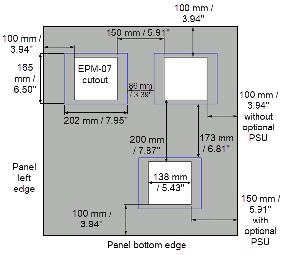 Note - Cutout dimensions follow a upper tolerance of +1 mm (+ 0.04 ").
EPM-15
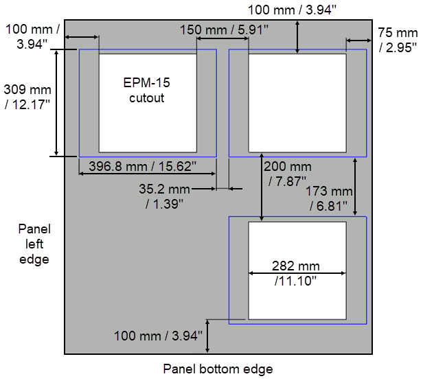 Note - Cutout dimensions follow a upper tolerance of +1.3 mm (+ 0.05 ").
Minimum recommended enclosure depth
Allows sufficient clearance for module assembly and maintenance:
EPM Device Rear Clearance Required EPM-07 260 mm (10.24") EPM-15 247 mm (9.72") -
Verify Electrical Requirements - To ensure compliance and to avoid hazards:
 CAUTION
EQUIPMENT OPERATION HAZARD
Observe all electrostatic discharge precautions before handling the unit.
Failure to follow these instructions can result in injury or equipment damage
-
Confirm the power supply matches the recorder's voltage and current specifications.
-
Ensure proper grounding is available.
-
Check that input /output/ supply signals to be connected to I/O terminal block comply with electrical specifications of the I/O.
-
Ensure the wiring load on the I/O module stays within the slot’s power limit. Refer to Technical Data Sheets and Specifications for more details.
-
-
Plan Connectivity and Cabling - Map out cable routes and prepare correct cable length to avoid interference and clutter.
Tip - Label both ends of each cable for easier troubleshooting later.
Software
Check that your operating system and applications meet the minimum installation requirements. This can help prevent crashes, licensing issues and missing dependencies:
| Item | Minimum Requirement | Recommended |
|---|---|---|
| Web Browser | Google Chrome and Microsoft Edge version 148 or higher | Google Chrome and Microsoft Edge version 148 or higher |
Last update - June 2026