Calibrating I/O Modules
Calibration ensures that input and output (I/O) modules provide accurate and reliable measurements. It involves comparing an I/O value with a reference standard of known accuracy, and where necessary, applying a correction to minimize any discrepancy. Calibration can correct or compensate discrepancies introduced by the system, including sensor characteristics, wiring, installation changes, or other factors that differ from the factory calibration conditions. Each calibration event is recorded with a date to provide traceability.
 CAUTION CAUTION |
|---|
|
RECALIBRATION REQUIRED Review the user calibration and repeat it if necessary after changing any Analog Input (AI) configuration parameters. Failure to follow this instruction can result in incorrect Analog Input readings |
Calibrating I/O modules is essential for several reasons:
-
Accuracy - Ensures that input and output values remain within specified accuracy limits, supporting reliable process measurement and control.
-
Compliance - Demonstrates compliance with statutory and applicable industry standards, providing help in avoiding penalties or product recalls.
-
Safety - Ensures that measurements used for monitoring and control remain within specified accuracy limits, reducing operational risk and incorrect process decisions.
-
Quality Control - Supports reliability and consistency of measurements, helping maintain process and product quality.
-
Maintenance - Identifies potential issues early, such as measurement drift or other performance changes before they significantly affect the process, avoiding costly failures.
Pre-requisites
-
Controlled, calibrated reference equipment such as a calibrated furnace or bath for calibrating a complete temperature loop, or
-
A precision electrical signal source capable of applying a defined signal to the input through the sensor wiring.
To calibrate an I/O module:
-
From the EPM User Interface screen, select Options
 - Device I/O - Hardwired I/O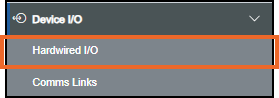
-
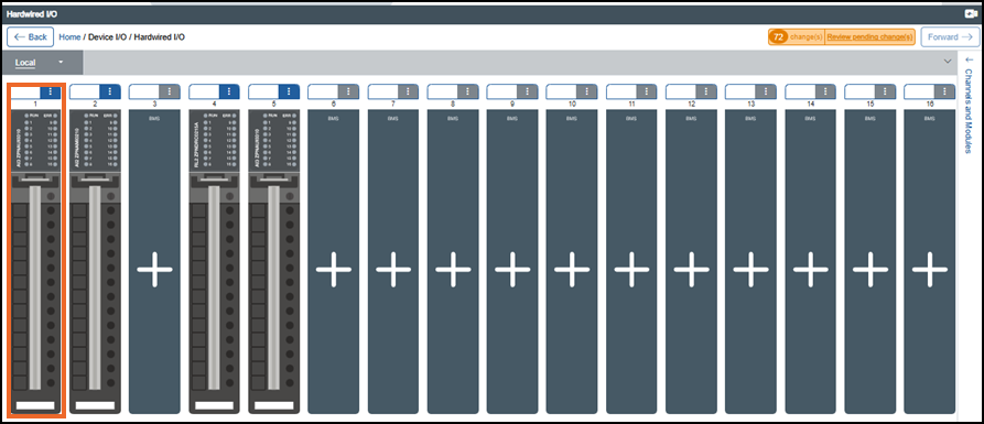
The Hardwired I/O screen displays, select an appropriate analog input module
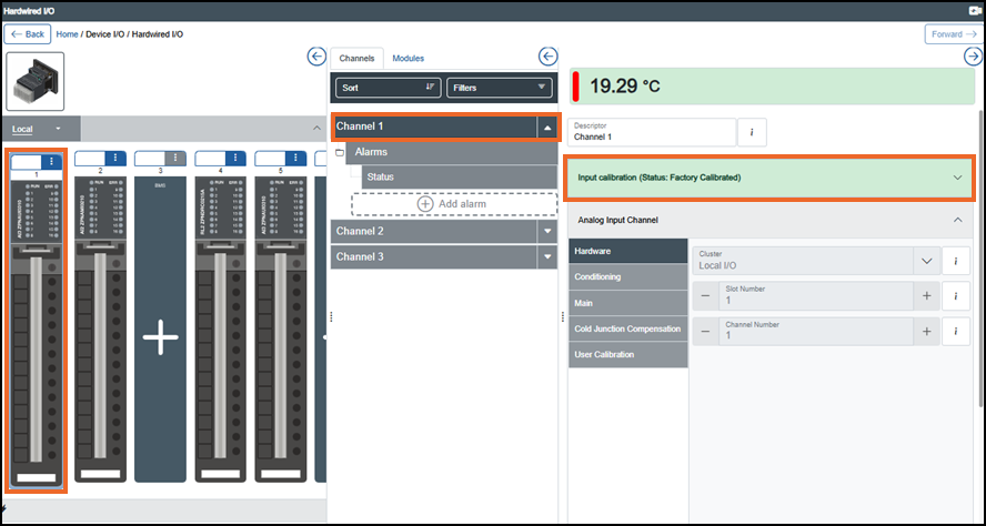
- Select the required channel from the Channels tab. The Input calibration screen displays on the right-hand side
-
From Input calibration, select Expand
 to display the calibration options, then select Start
  to begin the calibration
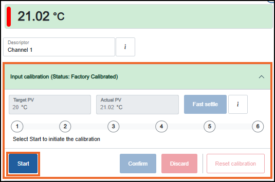 Note - By default, all analog input modules are factory calibrated.Note - The Input Calibration header displays the last successful calibration (factory or user calibration) and the date.
 -
The Start user calibration screen displays, select Continue:
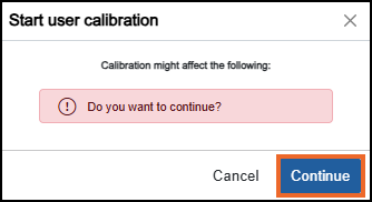 Tip - The Operator Panel displays 'Calibrating' as the status.Tip - Select Discard
 at any time to stop calibration and restore the previous calibration state (factory or user calibration).
 -
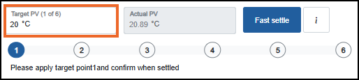
The calibration indicator highlights each calibration point in sequence. The number of calibration target points (2 - 6) is defined by the User Calibration Point Count configured for the channel, see the User Calibration Point Count option in the Configuring an Analog Input Channel for details.
For each highlighted calibration point, enter the Target PV in engineering units. The target PV is the process value that corresponds to the signal applied to the input in the next step:
-
At the corresponding sensor location, apply a known reference signal measurement that corresponds to the Target PV. This can be performed by either :
-
Using controlled calibrated equipment, for example, a calibrated furnace or bath for temperature loops, or
-
Injecting a precision electrical signal directly into the sensor wiring.
-
-
Wait until the Actual PV on the calibration panel stabilizes as close as possible to the Target PV within the accuracy of the reference equipment. When the Actual PV is stable, select Confirm to save the new calibration point
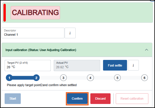 Tip - Select Fast settle
 to temporarily disable or bypass input filters for faster stabilization.
 -
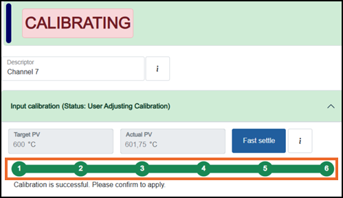
Repeat Step 5 to Step 7 until all calibration points are completed. The target indicator turns green:
-
After successful calibration, the channel is marked as 'User Calibrated' along with the calibration date:

Use the Reset calibration
 option if required to delete all stored user calibration data (old/new) for the channel/module and restore it to its original factory calibration values.Note - The Reset calibration option is only available when a channel is in a user calibrated state and no calibration is currently in progress.
Last update - September 2026