Configuring an Analog Input Channel
An Analog Input Channel outputs a linearized analog process variable by processing inputs from various analog sensors or devices. It is designed to handle a wide range of input types, perform linearization, scaling and compensation for example, Cold Junction Compensation. It also manages sensor diagnostics and status.
To configure an Analog Input Channel:
-
From the EPM User Interface screen, select Options
 - Device I/O - Hardwired I/O: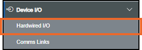
-
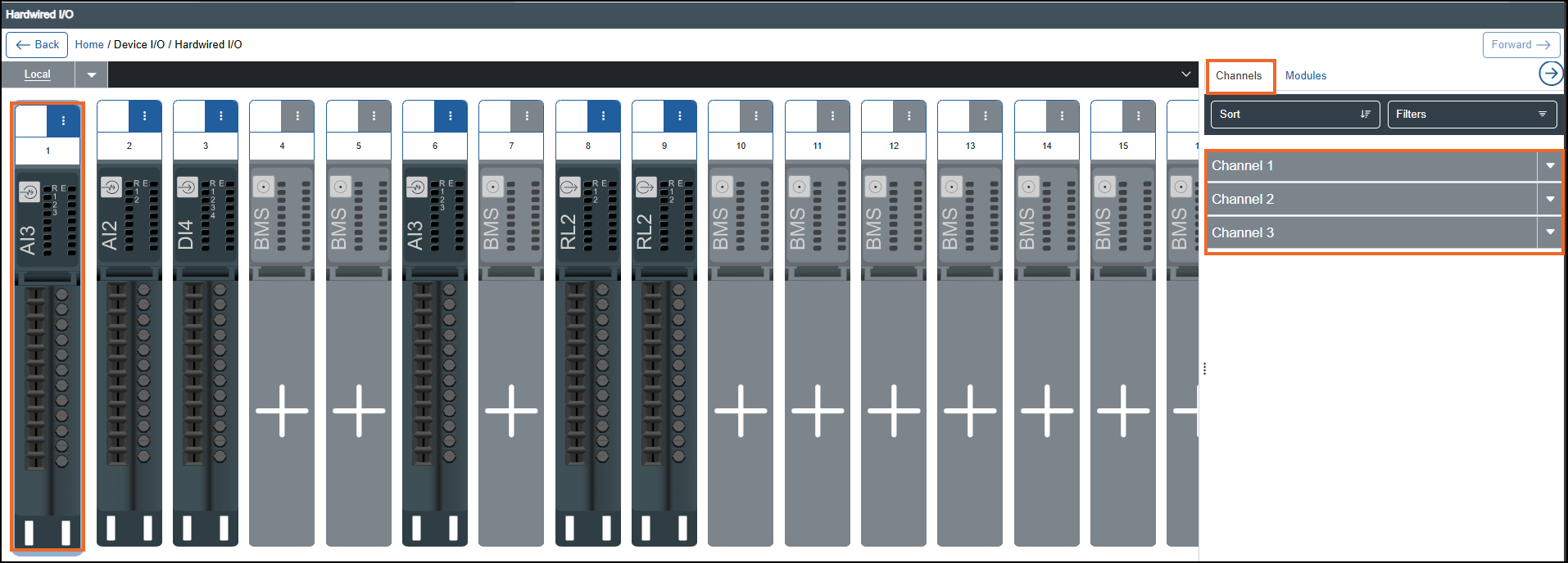
The Hardwired I/O screen displays, select the required Analog Input module from the left-hand side and the associated channels display on the right-hand side in the Channels tab:
-
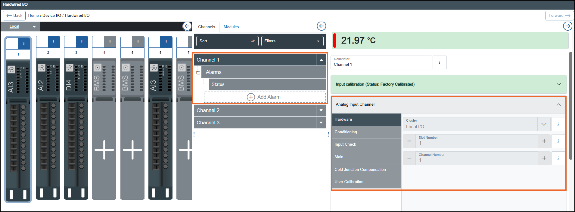
Select the required Analog Input Channel and the properties display on the right-hand side:
-
If you are not already in Configuration lock, the Configuration lock screen displays
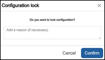
Enter a reason if required and then select Confirm
 . The system configuration is now locked pending the submission of your update and the Configuration Locked
  icon displays on the status bar.Note - Configuration lock does not affect the operation of the EPM device.See Configuration Lock for details.
 -
Complete as required:
-
Analog Input Channel - Select Expand
 if it does not expand automatically:
-
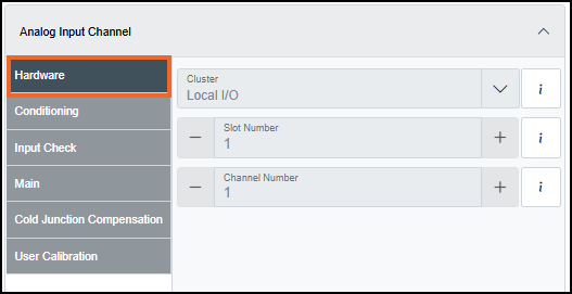
Hardware:
-
Cluster - Cluster where the module is plugged in, for example, Local I/O.
-
Slot Number - Slot number (1…n) where the module is plugged in.
-
Channel Number - Channel number (1…n) in the module.
-
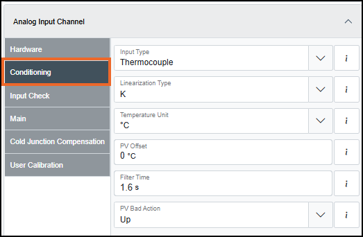
Conditioning:
-
Input Type (options vary depending on AI2 or AI3 channel) - Select the type of sensor/signal connected to the device: Off, Thermocouple, Millivolt, Volt, Milliampere, Zirconia, RTD
 resistance temperature detectors - sensors that use electrical resistance of a substance to measure temperature. 2 Wires, RTD 3 Wires, Resistance 2 Wires, Resistance 3 Wires, Contact Closure, Pyrometer.
 -
Linearization Type - Select the type of linearization method to be applied: B, C, D, E, G2, J, K, L, N, R, S, T, U, NiMo/Nico, Ni/NiMo, Platinel, Pt20% Rh/Pt 40% Rh, MoRe, Cu10, Cu53, JPT100, Ni100, Ni120, PT100, PT100a, PT1000, Linear, Square Root, Power 3/2, Power 5/2, Invert, Custom.
-
Temperature Unit - Select the unit (oC, oF, K, or oR)
Centigrade, Fahrenheit, Kelvin or Rankine for the PV and associated parameters when a Linearization Type producing a temperature is selected, for example, J, N, PT100. -
PV Offset - Enter the fixed value to be added to or subtracted from the process variable in the selected Temperature Unit.
-
PV Range High - Enter the PV range high value in the entered engineering Unit in Chart and presentation settings.
Note - Not available when the Input Type is set to Thermocouple, RTD or Contact Closure. -
PV Range Low - Enter the PV range low value in the entered engineering Unit in Chart and presentation settings.
Note - Not available when the Input Type is set to Thermocouple, RTD or Contact Closure. -
Input Range High - Enter the linear input high value in the selected Input Type unit.
Note - Not available when the Input Type is set to Thermocouple, RTD or Contact Closure. -
Input Range Low - Enter the linear input high value in the selected Input Type unit.
Note - Not available when the Input Type is set to Thermocouple, RTD or Contact Closure. -
Filter Time (in seconds) - Enter the filter time constant (0 - 1000, '0' value disables filtering).
-
PV Bad Action - Select the behavior of PV when the PV status becomes Bad except when the Input Type is set to Off:
-
Up - PV equals to PV Range High.
-
Down - PV equals to PV Range Low.
-
Fixed - PV equals to PV Bad Fixed Value.
-
PV Bad Fixed Value (only available when the Fixed option is selected) - Enter the fixed value in engineering unit.
Tip - The value must be within the configured PV Range.
-
-
-
Emissivity (only available when the Input Type is set to Pyrometer) - Enter the correction factor value to be applied to compensate for the emissivity of the object being measured, greater than zero (for a perfect reflector) and less than 1 (for a perfect emitter).
-
Shunt Value (only available for AI3 channels when the Input Type is set to Milliampere) - Enter the shunt resistor value to be used for the Milliampere Input Type.
Note - For AI2 channels, this value is fixed to 249 Ω .
-
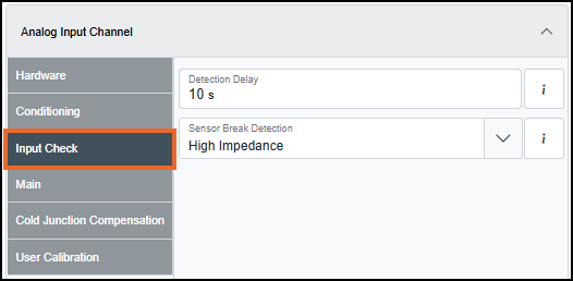
Input Check:
-
Detection Delay (in seconds) - Enter the delay time between a detection and the related status indication, applicable to Sensor Break Detection, Input Range Detection, and NE43.
-
Sensor Break Detection (only available when the Input Type is set to Thermocouple, Millivolt, Volt (only when the Input Range Low and Input Range High is between -1V and +1V), or Pyrometer) - Select the type of operation for the detection of a sensor break:
-
No sensor break detection - No sensor break detection in hardware.
-
When Impedance High - Sensor break is detected in hardware, and sensor break becomes active at a high impedance, for example, impedance >= 5 kΩ.
-
When Impedance HighHigh - Sensor break is detected in hardware, and sensor break becomes active at a higher impedance, for example, impedance >= 20 kΩ.
-
-
NE43 (only available when the Input Type is set to Milliampere) - NE43 detection for mA inputs.
-
Input Range High Detection (not available when the Input Type is set to Thermocouple, RTD or Contact Closure) - Select the type of operation for the Input Range High Detection:
-
Off - No Input Range Detection.
-
Percent Threshold - Detects the input high range based on the specified percentage threshold.
Note - When Percent Threshold is selected, the absolute threshold is calculated as PV Range High + Percent Threshold value x (PV Range High - PV Range Low). -
Electrical Threshold - Detects the input high range based on the specified electrical threshold.
-
Input Range High Threshold (only available when the Input Range High Detection option is not Off) - Enter the high threshold value for the Input Range High Detection.
Note - When Electrical Threshold is selected, enter the high threshold value in the selected Unit Type such as mA, V, Ohm. If Percent Threshold is selected, enter the high threshold value in percentage.
-
-
-
Input Range Low Detection (not available when the Input Type is set to Thermocouple, RTD, or Contact Closure) - Select the type of operation for the Input Range Low Detection:
-
Off - No Input Range Detection.
-
Percent Threshold - Detects the input low range based on the specified percentage threshold.
Note - When Percent Threshold is selected, the absolute threshold is calculated as PV Range Low - Percent Threshold value x (PV Range High - PV Range Low). -
Electrical Threshold - Detects the input low range based on the specified electrical threshold.
-
Input Range Low Threshold (only available when the Input Range Low Detection option is not Off) - Enter the low threshold value for the Input Range Low Detection.
Note - When Electrical Threshold is selected, enter the low threshold value in the selected Unit Type such as mA, V, Ohm. If Percent Threshold is selected, enter the low threshold value in percentage.
-
-
-
-
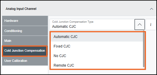
Cold Junction Compensation (only available when the Input Type is set to Thermocouple):
-
Cold Junction Compensation Type - Select the type of cold junction compensation strategy adopted:
-
Automatic CJC - Automatic (Internal CJ).
-
Cold Junction Automatic Temperature (only available when the Automatic CJC option is selected) - Enter the temperature measured at the rear terminal block.
-
-
Fixed CJC - Fixed and determined by Cold Junction Fixed Temperature value.
-
Cold Junction Fixed Temperature (only available when the Fixed CJC option is selected) - Enter the fixed temperature value.
-
-
No CJC - No cold junction compensation.
-
Remote CJC - Remote CJC determined by Cold Junction Temperature Input value.
-
Cold Junction Temperature Input (only available when the Remote CJC option is selected) - Enter the temperature value.
-
-
-
-
-
From Chart and presentation settings, select Expand
if it does not expand automatically, and then complete the following:-
General Settings:

-
Units - Enter an engineering unit, for example, °C, psi or Volts, up to a maximum of six characters. For information on entering special characters, see How do I enter special characters?.
Tip - The unit displays with the channel value on the Operator Panel. -
Number Format - Select either:
-
Numeric - Displays values in decimal format, for example, 12345.6789 displays as 12,345.6789.
-
Scientific - Displays values in scientific notation, useful for very large or very small numbers. Numbers display as a coefficient multiplied by a power of 10, for example, 12345.6789 displays as 1.23456789E+4.
-
-
Decimal Places - Enter the value, or use the Plus
 and Minus
  to set the decimal place (0 to 6).
 -
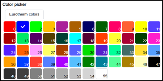
Color - Select a color from one of the 56 available colors:
-
-
Scale & Zone Settings:
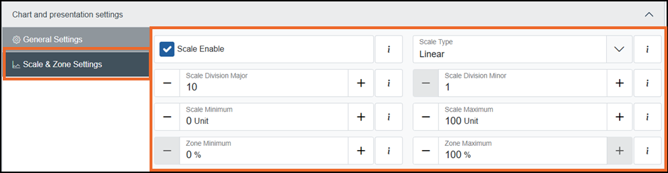
To set the chart scale and zoning for this channel:
-
Scale Enable - Tick to enable scale configuration and specify the scale type and the number of divisions required:
-
Scale Type (available only when Scale Enable is enabled) - Select one of the following options:
-
Logarithmic - Divisions are displayed using a logarithmic scale. This option is suitable for analyzing data spanning multiple orders of magnitude.
-
Linear - Divisions are displayed at equal intervals. This option is ideal for displaying uniformly distributed data:
-
Scale Division Major (available only when Scale Type is Linear) - Enter a value, or use the Plus
and Minus to set the major divisions to be included on the chart (valid range 1 to 20). -
Scale Division Minor (available only when Scale Type is Linear) - Enter a value, or use the Plus
and Minus to set the minor divisions to be included on the chart (valid range 1 to 20).Note - Scale divisions have no impact on a chart grid, they are only for scale. The grid on the chart is defined by the division settings on the group, see Configuring Groups Settings for details.
-
-
-
-
Scale maximum (Unit) - Enter a value, or use the Plus
and Minus to set the upper limit of the scale's range. -
Scale minimum (Unit) - Enter a value, or use the Plus
and Minus to set the lower limit of the scale's range. -
Zone maximum (%) - Enter a value, or use the Plus
and Minus to set the percentage offset for the upper limit of the scale and trendline relative to the top of the chart (valid range 5 to 100). -
Zone minimum (%) - Enter a value, or use the Plus
and Minus to set the percentage offset for the lower limit of the scale and trendline relative to the bottom of the chart (valid range 0 to 95).Note - The minimum value must be less than the maximum value by 5 or more.Tip - The Zone settings offset a scale and its associated trendline relative to the chart grid. This is useful when displaying multiple trends with similar value ranges, which would otherwise overlap and become difficult to distinguish. For example, several digital trends switching between 0 and 1 can overlap, making them difficult to distinguish unless each is defined a different Zone.
-
-
 to configure an alarm on this channel, see Configuring an Alarm for further details.
Once complete, select Review pending changes  screen to review updates to the configuration, and submit them. See Reviewing and Submitting Changes for details if required.
Last update - July