AI2 Two Channel Isolated Analog Input Module Technical Data Sheet
This two channel isolated analog input module (AI2), is used for standard V and mA process inputs. Channel based isolated loop power supplies are provided to support 2-wire connection to field transmitters. It is commonly used for reading industrial process variables, for example, temperature or pressure.
| Number of channels |
|
| Compatible terminal block |
|
| Analog input type |
| Voltage |
±10 V |
| Current |
±20 mA |
|
| Input wiring mode |
|
| Analogue input resolution |
| Voltage Resolution 6uV (peak to peak) |
| Current Resolution 0.03uA (peak to peak) |
|
| Permitted overload on inputs |
| 30 V maximum voltage |
| 30 V at 50 mA maximum current |
|
| Input impedance |
| Voltage |
>10 MΩ |
| Current |
250 Ω + 10 Ω (typical) internal current protector |
|
| Sampling duration |
|
| Sensor power supply protection |
| Over current protection per channel |
| Short circuit protection on loop power supply per channel |
|
| Input diagnostic channel |
| Module field power fault detected |
| Module hardware fault detected |
| Loop power supply fault detected |
| ADC Range Underflow detected |
| ADC Range Overflow detected |
| Hardware fault detected |
| Calibration Invalid |
|
| Hart tolerance |
|
| Temperature drift |
| ±0.001 % full scale / °C (±0.0018 % full scale / °F) |
|
| Maximum accuracy at ambient 25°C (77° F) / maximum allowed temperature |
| <= 0.05 % full scale 25 °C (<= 0.05 % full scale 77 °F) |
| <= 0.1 % full scale -20 to 55 °C (<= 0.1 % full scale -68 to 131 °F) |
|
| Non-linearity |
|
| Common mode rejection |
|
| Sensor power supply |
| 19.2 to 30 Vdc sensor power supply |
| 24 Vdc isolated loop power |
|
| Current consumption |
| 36 mA at 24 Vdc on the bus current |
| 38.4 mA at 24 Vdc on the internal field current minimum |
| 246.1 mA at 24 Vdc on the internal field current maximum |
|
| Power dissipation |
1.3 W maximum at 24 Vdc |
| Isolation |
| Between channels |
530 Vac |
| Between channels and bus |
1500 Vac |
| Between channels and ground |
1500 Vac |
| Between channels and field power |
| No for sensor power supply |
| 1000 Vac for loop power supply |
|
| Between field power and bus |
1500 Vac |
|
| Maximum cable length |
| Unshielded |
Maximum length 30 m (98' 5") |
| Shielded |
Current maximum length 1000 m (3280' 10') |
| Shielded |
Voltage maximum length 200 m (656' 2') |
|
| Weight |
| Module |
47.6 g (1.68 oz) |
| Terminal Block |
47.7 g (1.68 oz) |
|
| Hot swap |
|
| Housing color |
|
| IP degree of protection |
|
| Product certification |
|
| Standards |
| EN/IEC 61326-1 |
| EN 61010-2-201 |
| UL 61010-2-201 |
|
| Directives |
| 2014/30/EU - Electromagnetic compatibility |
| 2014/35/EU - Low voltage |
| 2011/65/EU, 2015/863/EU RoHS |
|
| Operating temperature |
| 0 to 55 °C (32 to 131 °F) |
|
| Storage temperature |
| -5 to 60 °C (23 to 140 °F) |
|
| Relative humidity |
| 5 % to 95 % without condensation |
|
| Operating altitude |
| 0 to 2000 m (0 to 6561 ft) |
|
| Pollution degree |
|
| Vibration |
|
| Shock |
|
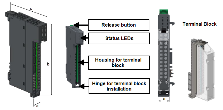
Dimensions
| a |
15 mm (0.59") |
| b |
100 mm (3.94") |
| c |
66 mm (2.60") |
| c plus Terminal Block |
101.9 mm (3.98") |
|
AI2 Two Channel Isolated Analog Input Terminal Wiring
|
INOPERABLE EQUIPMENT
Do not connect the 24 Vdc sensor power supply with the 24 Vdc loop power supply of the module
Failure to follow these instructions can result in equipment damage
|
|
HAZARD OF ELECTRICAL SHOCK, EXPLOSION OR ARC FLASH
Failure to follow these instructions will result in death or serious injury
|
|
UNINTENDED EQUIPMENT OPERATION
Failure to follow these instructions can result in death, serious injury, or equipment damage
|
Tip - Where signal and power wiring cannot be separated, signal wiring should be shielded.
| 1 solid conductor |
0.2 to 2.5 mm² (American Wire Gauge (AWG) 24 - AWG 14) |
| 2 solid conductors |
0.2 to 1.5 mm² (AWG 24 - AWG 16) - both conductors must be the same cross section |
| 1 stranded conductor without ferrule |
0.2 to 2.5 mm² (AWG 24 - AWG 14) |
| 1 stranded conductor with single ferrule |
0.2 to 1.5 mm² (AWG 24 - AWG 16) |
| 2 stranded conductors with twin ferrule |
0.2 to 0.75 mm² (AWG 24 - AWG 20) |
Note - Minimum individual conductor size in stranded connectors when no ferrule is used is a cross section of 0.05 mm² (AWG 30).
Terminal block captive screws are not supplied tightened and must be tightened to 0.5 to 0.6 Nm (0.30 lb-ft) using a flat tipped screwdriver with a diameter of 3.5 mm (0.14"). Stripping length for all cable types is 10 mm (0.39").
|
INOPERABLE EQUIPMENT
Do not physically wire the analog channel for a voltage signal and configure the channel for a current signal.
Failure to follow these instructions can result in equipment damage
|
You may damage the analog circuit if you do not verify that the physical wiring of the analog circuit is compatible with the software configuration for the analog channel.
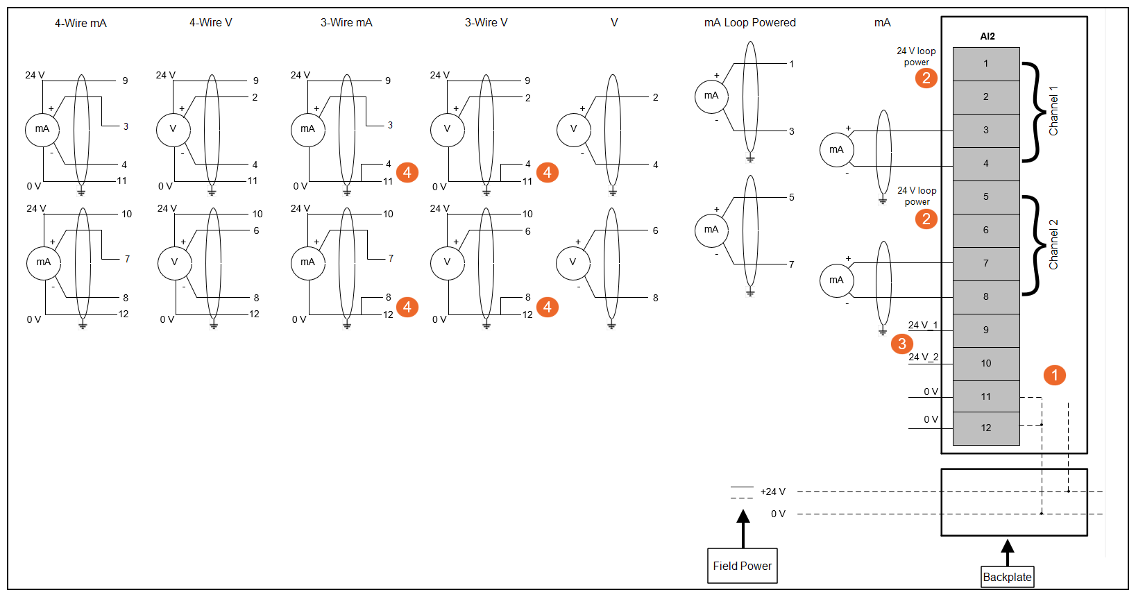
Note - Shielded cable not required if the cable connected to the I/O terminals is under 30 m (98' 5") in length.
| 1 |
The sensor power outputs, pins 1, 3, 5 and 7, are protected within the module by a common self-resetting eFuse (nominally 500 mA). The module has two power supply diagnostics flags, one for the field power incoming from the backplate, and one for the outgoing power to the sensor. |
| 2 |
24 V is isolated loop power |
| 3 |
24 V_1 and 24 V_2 is Sensor power |
| 4 |
For 3-wire sensors, note the connections required between pins 4 and 11, and 8 and 12 |
Status LEDs
| Module is energized, configured and operational. |
Green |
Off |
Off |
| Channel is activated |
Green |
Off |
Green |
| Channel is deactivated |
Green |
Off |
Off |
| 24 Vdc field power error detection |
| Sensor power supply error detection |
|
Green |
Red - Regular flash (one flash per second) |
Off |
| No power |
Off |
Off |
Off |
| Module detects a system error |
Off |
Red |
Off |
| Module was not configured during initialization |
Green - Slow flash (one flash per 2 seconds) |
Off/Red - Slow flash (one flash per 2 seconds) |
Off |
| Firmware is being updated |
Green - Regular flash (one flash per second) |
Off |
Off |

 DANGER
 WARNING