AI3 Three Channel Isolated Universal Analog Input Module Technical Data Sheet
This three channel isolated analog input module (AI3) is a high precision universal analog input module, it accepts most standard industrial process inputs: mV, V, mA, thermocouple, resistance and resistance temperature detector (RTD). mA inputs require an external shunt resistor and an optional shunt assembly is available to assist with installation. The AI3 module is commonly used for reading industrial process variables, for example, thermocouple temperatures, pressures, and flowrates.
This three channel analog input module (AI3) is a high precision universal analog input module, it accepts most standard industrial process inputs:
| Number of channels |
|
| Compatible terminal block |
|
| Input range |
| Voltage |
±40 mV, ±80 mV, ±1 V, 0 to 2 V, ±20 V |
| Current |
±20 mA |
| Resistance |
0 to 400 Ω / 0 to 4kΩ |
| Contact Closure |
Active < 3.2 kΩ, Inactive > 3.5 kΩ (2-Wire RTD connection) |
| Input impedance |
| 40 mV, 80 mV > 10 MΩ (typical) |
| 1 V, 0 to 2 V > 100 MΩ (typical) |
|
| Maximum input range |
Input range ±5% |
|
| Input wiring mode |
|
| Accuracy (ambient 25°C (77 °F) / (Full Operational 0 to 55°C (32°F - 131 °F)) (% full scale) |
| ±40 mV |
0.06 % / 0.11 % |
| ±80 mV |
0.05 % / 0.1 % |
| ±1 V |
0.05 % / 0.1 % |
| 0 to 2 V |
0.05 % / 0.1 % |
| ±20 V |
0.09 % / 0.2 % |
| ±20 mA (Assuming external shunt 0.05% tolerance and 10 ppm/°C (5.6 ppm/°F ) drift
) |
0.11 % / 0.2 % |
| 0 to 400 Ω / 0 to 4kΩ |
0.05 % / 0.1% |
| Internal cold junction compensation measurement(CJC) |
0.5 °C / 0.7 °C (0.9 °F/1.3 °F) |
|
| CJ rejection ratio |
|
| Offset and gain drift error |
| ±40 mV, ±80 mV, ±1 V, 0 to 2 V |
0.16 μV/°C + 12 ppm/°C (0.09 μV/°F + 6.7 ppm/°F) |
| ±20 V |
29 μV/°C + 32 ppm/°C (16.1 μV/°F + 17.8 ppm/°F) |
| ±20 mA (External 0.05% 10ppm Shunt) |
0.003 μA/°C + 22 ppm/°C (0.002 μV/°F + 9.9 ppm/°F) |
| 0 to 400 Ω / 0 to 4kΩ |
0.001 Ω/°C + 7 ppm/°C (0.001 Ω/°F + 3.9 ppm/°F) |
|
|
Thermocouple long term drift
Types T, R, B, E, J, K, N, S, C and M
|
| Over a 90 day interval, suitable for Class 1 furnace AMS2750 Applications: |
| < 1.1°C (33.98°F) for "Control, monitoring and recording Instruments" |
| < 0.6°C (33.08°F) for "Field Test Instruments" |
|
| Resolution (peak to peak - no software filter) |
| Voltage |
0.45 μV on ±40 mV |
| |
0.65 μV on ±80 mV |
| |
3.3 μV on ±1 V |
| |
3.3 μV on 0 to 2 V |
| |
70 μV on ±20 V |
| Current |
0.1 μA on ±20 mA |
| Resistance |
0.004 Ω on 400 Ω |
| Resistance |
0.014 Ω on 4 kΩ |
|
| Protection |
Overvoltage protection maximum ±30 Vdc no damage |
| Input diagnostic |
| Broken wire on mV / 1 V / TC / Resistance / RTD / input types |
| AC sensor break, Low > 5 kΩ, High > 20 kΩ , 0 to 2 V offline impedance measurement |
| RTD lead resistance >22 Ω |
|
| Hart tolerance |
|
| Cold junction compensation measurement(CJC) |
| Temperature sensor on board and terminal block |
|
| Differential mode rejection |
|
| Common mode rejection |
|
| Non-linearity (relative to full scale) |
| ±40 mV, ±80 mV, ±1 V; 0 to ±2 V, ±20 V |
< 0.0008 % |
| 0 to 400 Ω / 0 to 4kΩ |
< 0.004 % |
|
| Input filter |
| Software run-time configurable filter 0 (Off) to 1000 seconds - Default 1.6 s |
|
| Current consumption |
| 36.0 mA at 24 Vdc on the bus current |
| 18.0 mA at 24 Vdc on the internal field current minimum |
| 21.6 mA at 24 Vdc on the internal field current maximum |
|
| Power dissipation |
|
| Isolation |
| Between channels |
1500 Vac Basic |
| Between channels and bus |
3000 Vac Reinforced |
| Between channels and ground |
3000 Vac Reinforced |
|
| Maximum cable length |
| Unshielded |
Maximum length 30 m (98' 5") |
| Shielded |
Current maximum length 1000 m (3280' 10") |
| Shielded |
Voltage maximum length 200 m (656' 22") |
|
| Weight |
| Module |
44.4 g (1.57 oz) |
| Terminal Block |
48.0 g (1.69 oz) |
|
| Hot swap |
|
| Housing color |
|
|
Thermocouple
| Temperature scale |
|
| Cold junction Compensation types |
| Automatic (Internal CJC measurement), Fixed (user entered value) , None, Remote (Software configured) |
|
| Upscale/downscale drive |
| User defined Value, Range High, Range Low |
|
| B |
|
|
| 0 to 400 (32 to 752) = 1.7 (3.06) |
| 400 to 1820 (752 to 3308) = 0.03 (0.054) |
|
| C |
|
|
|
| D |
|
|
|
| E |
| -270 to 1000 (-454 to 1832) |
|
|
|
| G2 |
|
|
|
| J |
| -210 to 1200 ( -346 to 2192) |
|
|
|
| K |
| -270 to 1372 (-454 to 2501.6) |
|
|
|
| L |
| -200 to 900 (-328 to 1652) |
|
| DIN43710:1985 (To IPTS68) |
|
|
| N |
| -270 to 1300 (-454 to 2372) |
|
|
|
| R |
| -50 to 1768 (-58 to 3214.4) |
|
|
|
| S |
| -50 to 1768 (-58 to 3214.4) |
|
|
|
| T |
| -270 to 400 (-454 to 752) |
|
|
|
| U |
| -200 to 600 (-328 to 1112) |
|
|
|
| NiMo/NiCo |
| -50 to +1410 (-58 to 2570) |
|
|
|
| Ni/NiMo |
|
|
|
| Platinel |
|
|
|
| Pt20%Rh/ Pt40%Rh |
|
|
|
| MoRe |
|
|
|
| Temperature scale |
|
| Influence of lead resistance |
| Matched - Negligible |
| Mismatched - 1 Ω/Ω |
|
| Measurement source current |
|
| Cu10 |
|
|
|
| Cu53 |
|
|
|
| JPt100 |
| -220 to 630 (-364 to 1166) |
|
|
|
| Ni100 |
|
|
|
| Ni120 |
|
|
|
| Pt100 |
| -200 to 850 (-328 to 1562) |
|
|
|
| Pt100a |
| -200 to 600 (-328 to 1112) |
|
|
|
| Pt1000 |
| -200 to 600 (-328 to 1112) |
|
|
|
| IP degree of protection |
|
| Product certification |
|
| Standards |
| EN/IEC 61326-1 |
| EN 61010-2-201 |
| UL 61010-2-201 |
|
| Directives |
| 2014/30/EU - Electromagnetic compatibility |
| 2014/35/EU - Low voltage |
| 2011/65/EU, 2015/863/EU RoHS |
|
| Operating temperature |
| 0 to 55 °C (32 to 131 °F) |
|
| Storage temperature |
| -5 to 60 °C (23 to 140 °F) |
|
| Relative humidity |
| 5 % to 95 % without condensation |
|
| Operating altitude |
| 0 to 2000 m (0 to 6561 ft) |
|
| Pollution degree |
|
| Vibration |
|
| Shock |
|
Dimensions
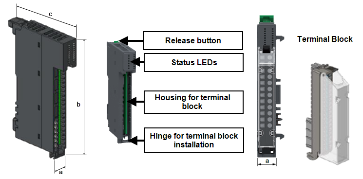
| a |
15 mm (0.59") |
| b |
100 mm (3.94") |
| c |
66 mm (2.60") |
| c plus Terminal Block |
101.9 mm (3.98") |
|
Shunt Assembly
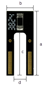
|
| Resistance |
|
| Tolerance |
|
| Thermal stability |
|
| Connector system |
| Blade 18 mm (0.7")long, 2.3 mm (0.09") wide and 0.8 mm (0.03") thick. |
| Bare conductor <1.4 mm (0.06") |
|
|
| |
|
Tip - We recommend the use of blade terminals with the AI3 shunt board:
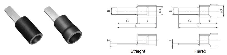
AI3 Universal Analog Input Terminal Wiring
|
HAZARD OF ELECTRICAL SHOCK, EXPLOSION OR ARC FLASH
Failure to follow these instructions will result in death or serious injury
|
|
UNINTENDED EQUIPMENT OPERATION
Failure to follow these instructions can result in death, serious injury, or equipment damage
|
Tip - Where signal and power wiring cannot be separated, signal wiring should be shielded.
| 1 solid conductor |
0.2 to 2.5 mm² (American Wire Gauge (AWG) 24 - AWG 14) |
| 2 solid conductors |
0.2 to 1.5 mm² (AWG 24 - AWG 16) - both conductors must be the same cross section |
| 1 stranded conductor without ferrule |
0.2 to 2.5 mm² (AWG 24 - AWG 14) |
| 1 stranded conductor with single ferrule |
0.2 to 1.5 mm² (AWG 24 - AWG 16) |
| 2 stranded conductors with twin ferrule |
0.2 to 0.75 mm² (AWG 24 - AWG 20) |
Note - Minimum individual conductor size in stranded connectors when no ferrule is used is a cross section of 0.05 mm² (AWG 30).
Terminal block captive screws are not supplied tightened and must be tightened to 0.5 to 0.6 Nm (0.30 lb-ft) using a flat tipped screwdriver with a diameter of 3.5 mm (0.14"). Stripping length for all cable types is 10 mm (0.39").
|
INOPERABLE EQUIPMENT
Do not physically wire the analog channel for a voltage signal and configure the channel for a current signal.
Failure to follow these instructions can result in equipment damage
|
Note - You may damage the external shunt resistor if you do not verify that the physical wiring of the external shunt resistor.
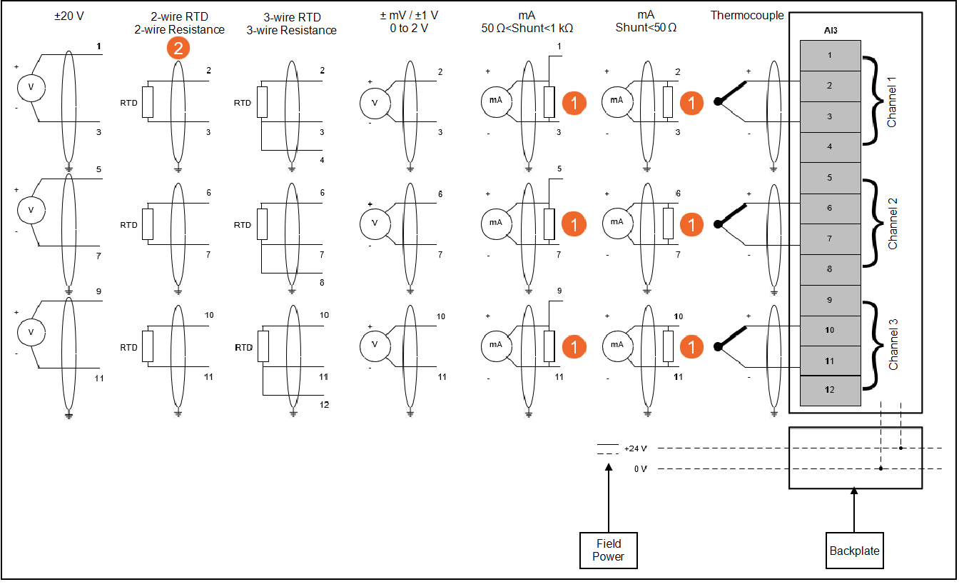
Note - Shielded cable not required if the cable connected to the I/O terminals is under 30 m (98' 5") in length.
| 1 - Shunt Resistor
|
This is required for mA inputs. The parameter configuration defaults to 49.9 Ω to match the value of the EPM Shunt Assembly (available separately), if a different resistor is used, its value must be entered in the parameter configuration. Shunt resistors below 50 Ω use the ±1 V range and resistors above 50 Ω use the ±20 V range. For the best results, use a resistor with a value less as close to but not exceeding 50 Ω for the most demanding applications. Ensure the terminals used match the value of resistor selected. |
| 2 - Contact Closure
|
This input type uses the 2-wire resistance input arrangement to detect the state of a volt free contact (VFC) as open/closed. This is provided for legacy use cases and the preferred connection method is to use a digital input module type because to provide a current through the contacts that is designed to work over a wide range of conditions. The resistance based approach used by the AI3 only provides a very small current and the switching of the VFC may not be reliably detected, for example, contacts becoming dirty over time. |
Status LEDs
| Module is energized, configured and operational. |
Green |
Off |
Off |
| Channel is activated |
Green |
Off |
Green |
| Channel is deactivated |
Green |
Off |
Off |
| 24 Vdc field power error detection |
| Sensor power supply error detection |
|
Green |
Red - Regular flash (one flash per second) |
Off |
| No power |
Off |
Off |
Off |
| Module detects a system error |
Off |
Red |
Off |
| Module was not configured during initialization |
Green - Slow flash (one flash per 2 seconds) |
Off/Red - Slow flash (one flash per 2 seconds) |
Off |
| Firmware is being updated |
Green - Regular flash (one flash per second) |
Off |
Off |

 DANGER
 WARNING