EPM Data Management - Technical Data Sheet
|
EPM-15
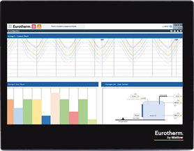
|
|
|
EPM-07
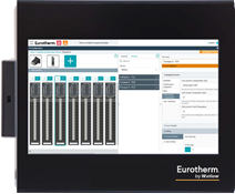
|
|
EPM Data Management delivers the following key features:
- Versatile color touchscreen display
|
|
- Modular, hot-swappable configurable I/O
|
|
- Multiple languages supported - English, French, German, Italian and Spanish.
|
|
| EPM-07 screen |
| EPM-15 screen |
|
| 7" Widescreen Thin Film Transistor (TFT) display (800 x 480 pixels) 16.7 M colors |
| 15" Widescreen TFT display (1920 x 1080 pixels) 16.2 M colors |
|
| I/O slots |
|
| Supported I/O module types, see EPM Solution I/O Modules for details. |
| AI3 - 3 Channel Isolated Universal Input Module |
| AI2 - 2 Channel Isolated Analog Input Module |
| DI4 - 4 Channel Digital Input Module |
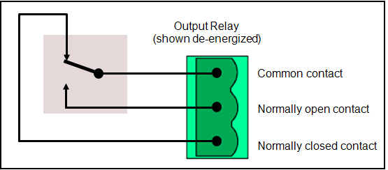
| RL2 - 2 Channel Change Over (Form C) Relay Output Module |
| BMS Blanking Module Single Width |
|
| Maximum analog input channels |
|
| Groups |
|
| Auditor features |
| Designed to meet the FDA Regulation 21 CFR Part 11 for Electronic Records and Signatures requirements. |
| Audit trail, a sub-set of Auditor provides a time stamped audit trail of events performed on the device |
|
| Maximum number of Maths, Counters, Timers and Totalizers |
|
| Alarms |
| Divided into predefined device alarms, for example Battery Low, and channel based user definable alarms, for example Absolute High |
| Filterable and sortable alarm summary views for system, process and all alarms |
| Up to 8 user defined alarms per channel |
|
| Batch Recording |
| Up to 30 batches |
| Each batch supports up to 20 data entry fields |
|
| Web clients |
| Up to 10 Web clients per device |
|
| Onboard storage |
|
| Power supply |
| dc - External SELV 24 Vdc, or |
| ac - 100 to 120 Vac or 200 to 240 Vac optional mains power supply unit (PSU) |
|
| Input voltage dc |
|
| Input current dc |
|
| Operating temperature |
| 0 to 55 °C (32 to 131 °F) |
|
| Storage temperature |
| -20 to 70 °C (-4 to 158 °F) |
|
| Operating and storage humidity |
| 5 % to 95 % Relative Humidity non-condensing |
|
| Vibration |
|
| Altitude |
| Maximum 2000 m (6561 ft) above sea level (ASL) |
|
| IEC 61326-1:2020 |
| Industrial Immunity, Class A Emissions |
|
| Protection |
| Front of panel |
IP66 / UL50E Type 4X indoor use only |
| Back of panel |
IP20 |
|
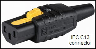
| Input connection |
| IEC C13 |
| Rewirable straight latching cord connector included |
|
| Input voltage |
| 100 to 120 Vrms ±10% |
| 200 to 240 Vrms ±10% |
|
| Input frequency |
50 to 60 Hz |
| Input current |
| 100 to 120 Vac 2.3 A |
| 200 to 240 Vac 1.1 A |
|
| Inrush current (typical) |
| 100 to 120 Vac 29 A |
| 200 to 240 Vac 60 A |
|
| Output voltage |
24 Vdc |
| Output current |
| 100 to 120 Vac 3.5 A / 84 W |
| 200 to 240 Vac 3.75 A / 90 W |
|
|
|
| Electrical safety approvals |
|
| UL file number |
|
|
Safety standards
|
| EN/IEC 61010-2-201 |
| UL 61010-2-201 |
| EN/IEC 61326-1 |
|
| Installation category II |
| The rated impulse voltage for equipment on nominal 230 Vac mains is 2500 Vac |
|
| Pollution degree 2 |
| Normally, only non-conductive pollution occurs. Occasionally, however, a temporary conductivity caused by condensation shall be expected |
|
| Proposition 65 |
These devices contain lead and nickel known to the State of California to cause cancer, birth defects or other reproductive harm |
| EU RoHS directive |
2011/65/EU, 2015/863 compliant with exemptions |
| RoHS exemption information |
Exemption used 6(a)-I,6(c),7(a),7(a)-I,7(c)-I, 7(c)-V |
| China RoHS regulation |
Compliant |
| REACH |
Under Article 33 of the REACH Regulation, his product contains SVHCs > 0.1% w/w |
| TSCA |
Substance(s) Present Above Threshold with Exemption |
| POP |
This product does not contain intentionally added (POP) Persistent Organic Pollutants |
| PFAS |
This product does not contain intentionally added per- and polyfluoroalkyl substances (PFAS) |
| Mercury free |
Compliant |
| Type |
|
| Replacement period |
| 3 years if the device is powered |
| 1 year if the device is unpowered |
|
| Diagnostic |
Battery low indicator and Alarm |
| Function |
Real Time Clock (RTC) |
| Real Time Clock (RTC) accuracy |
≤3 parts per million (ppm) |
| Type |
Ethernet 10/100/1000 Base-T |
| EN1 Protocols |
| HTTPS |
| HTTP |
| FTP |
| SFTP |
| DHCP |
| SNTP |
| ICMP (ping) |
|
| FN1 and FN2 Protocols |
| Modbus TCP Server |
| DHCP |
| ICMP (ping) |
|
| Cable type |
Shielded Cat 5e or above |
| Maximum length |
100 m |
| Connector |
RJ45 |
| Isolation |
30 Vac Basic |
| IP Address allocation |
Fixed (user specified) or DHCP |
|
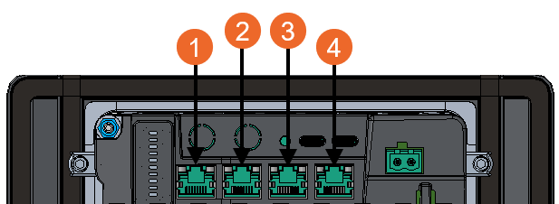
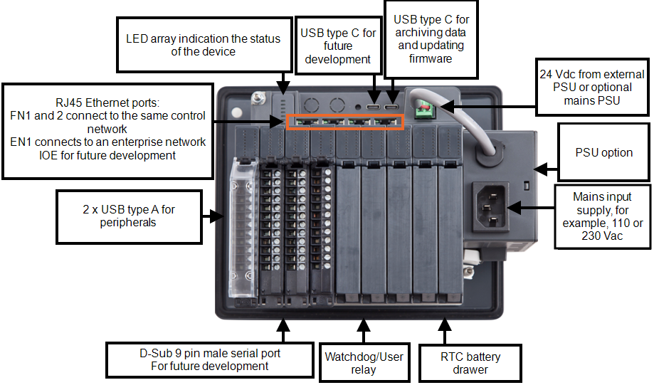
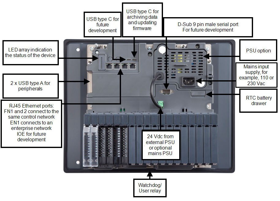
Note - EPM-07 shown, EPM-15 Ethernet connections are in a similar place with the same order.
|
| 1 - (FN1) |
Connects the EPM device to other process equipment, for example, PLC/PAC and analyzers, using a choice of industrial control protocols. Ports FN1 and FN2 are connected by an internal switch and share the same IP address |
| 2 - Field Network (FN2) |
Connects the EPM device to the same field network as FN1 |
| 3 - (EN1) |
Connects the EPM device to an IT or Enterprise network |
| 4 - Input/Output Extender ( IOE) |
Pending future development |
|
| Electrical durability |
| 400,000 cycles 2 A 250 Vac resistive |
|
| Minimum switching current |
|
| Switched voltage range |
| 24 to 250 Vac (47 - 63 Hz) |
| 5 to 125 Vdc |
|
| Switched current range |
| 2 A maximum at 24 Vdc or 250 Vac (resistive) |
| 0.4 A maximum at 125 Vdc (resistive) |
|
| Snubber |
|
| Isolation |
| Between contacts and +24 V Power supply 3000 Vac |
| Between contacts and ground 3000 Vac |
|
Note - Differences in load current, ambient temperature, load type and switching frequency impacts the number of operations.
Note - If you use the optional PSU, ensure you do not exceed the above power rating when configuring your system.
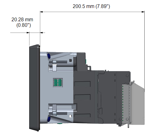
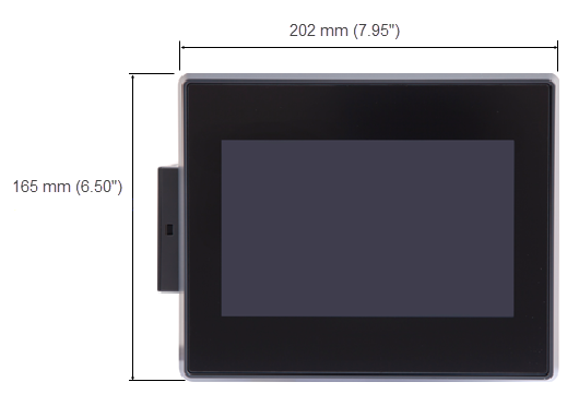
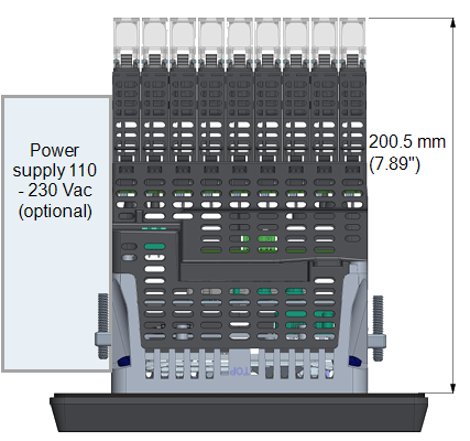
Dimensions for EPM-07
|
Side elevation with I/O
|
Front panel view (landscape)
|
|
Top elevation
|
|
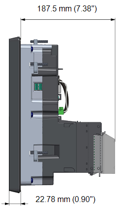
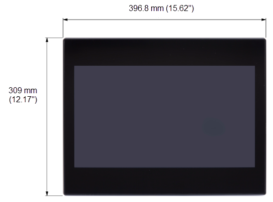
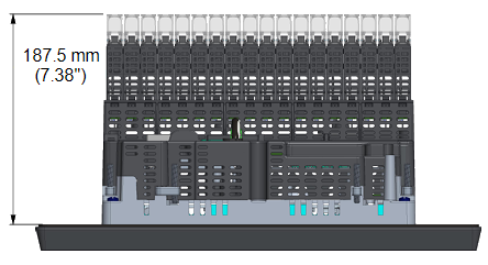
Dimensions for EPM-15
|
Side elevation with I/O
|
Front panel view
|
|
Top elevation
|
|
EPM Device Weights with no I/O modules
| EPM-07
|
2.22 Kg (4 lb 14.31 oz) |
| EPM-15
|
6.75 Kg (14 lb 14.10 oz) |
| Optional PSU |
0.27 Kg (9.5 oz) |
Panel Cutout and Clearance
The recommended minimum distances ensure:
-
Enough access for installation and maintenance.
-
Enough access to add and remove USB type A connectors for peripherals:
Note - Side to side cutout clearance can be reduced to 99.2 mm (3.90") on the EPM-07 if no USB type A access is required, this allows 35.2 mm (1.39") between bezels for structural integrity. Please be aware, reducing the clearance can reduce access for the assembly of the optional PSU.
-
Sufficient airflow for cooling.
-
The panel has enough structural support when its thickness is between 2 mm (0.079") and 10 mm (0.39"):
Note - If you are using trunking and earthing bars, additional space may be required.
EPM-07 Inside Panel View
Tip - The blue line below indicates the area of the front panel bezel.
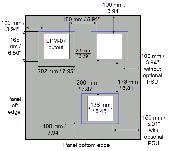
Note - Cutout dimensions follow a upper tolerance of +1 mm (+ 0.04 ").
EPM-15 Inside Panel View
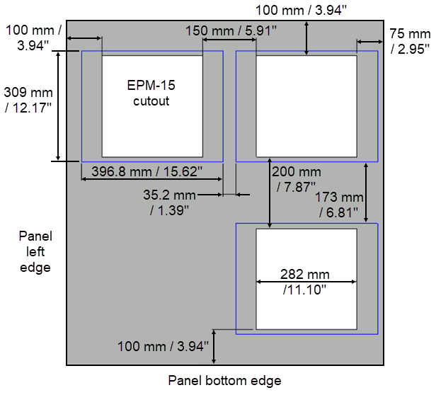
Note - Cutout dimensions follow a upper tolerance of +1.3 mm (+ 0.05 ").
Minimum recommended cabinet depth
Allows sufficient clearance for module assembly and maintenance:
| EPM-07
|
260 mm (10.24") |
| EPM-15
|
247 mm (9.72") |
|
Cable connections EPM-07
|
|
Cable connections EPM-15
|