RL2 Two Channel Relay Output Module Technical Data Sheet
This two channel digital relay output module (RL2) has two isolated Form C relays with normally open (NO) and normally closed (NC) contacts. It can be used to drive a wide variety of external devices, for example, light-emitting diodes (LEDs), lamps, inputs to an external devices and light loads.
| Number of channels |
|
| Compatible Terminal Blocks |
|
| Group of output channels |
|
| Digital output voltage |
| 24 to 250 Vac (47 - 63 Hz) |
| 5 to 125 Vdc |
|
| Digital output number |
| 2 relay outputs (form C with Normally Open /Normally Close contacts) |
|
| Output wiring mode |
|
| Digital output current |
| 2A maximum per output at 24 Vdc or 250 Vac (resistive) |
| 0.2A maximum per output at 125 Vdc (resistive) |
|
| Minimum switching current |
|
| Digital output frequency |
| 2 Hz for resistive load |
| 0.5 Hz for inductive load |
| 2 Hz for lamp load |
|
| Response time on output |
| <20 ms activation |
| <13 ms deactivation |
|
| Mechanical durability |
|
| [Ith] Conventional free air thermal current |
|
| Paralleling of outputs |
| Yes for logic links |
| Yes for redundant control of load |
|
| Electrical durability |
| 150,000 cycles 2 A 250 Vac |
| 150,000 cycles 2 A 30 Vdc |
| 300,000 cycles 1 A 250 Vac |
| 300,000 cycles 1 A 30 Vdc |
|
| Input diagnostic |
| Field power supply not detected |
|
| Power supply type |
| Bus power from power supply bus (24 Vdc) |
| Field power from power supply field (24 Vdc) |
|
| Current consumption |
| 27.6 mA at 24 Vdc on the bus current |
| 1.2 mA at 24 Vdc on the internal field current minimum |
| 21.4 mA at 24 Vdc on the internal field current maximum |
|
| Power dissipation |
|
| Isolation |
| Between channels |
1780 Vrms |
| Between channel and bus |
3000 Vrms |
| Between channels and ground |
3000 Vrms |
|
| Maximum cable length |
| Unshielded |
Maximum length 30 m (98' 5") |
| Shielded |
Current maximum length 1000 m (656' 2.4") |
|
| Weight |
| Module |
52.2 g (1.84 oz) |
| Terminal Block |
47.7 g (1.68 oz) |
|
| Hot swap |
|
| Housing color |
|
| IP degree of protection |
|
| Product certification |
|
| Standards |
| EN/IEC 61326-1 |
| EN 61010-2-201 |
| UL 61010-2-201 |
|
| Directives |
| 2014/30/EU - Electromagnetic compatibility |
| 2014/35/EU - Low voltage |
| 2011/65/EU, 2015/863/EU RoHS |
|
| Operating temperature |
| 0 to 55 °C (32 to 131 °F) |
|
| Storage temperature |
| -5 to 60 °C (23 to 140 °F) |
|
| Relative humidity |
| 5 % to 95 % without condensation |
|
| Operating altitude |
| 0 to 2000 m (0 to 6561 ft) |
|
| Pollution degree |
|
| Vibration |
|
| Shock |
|
Dimensions
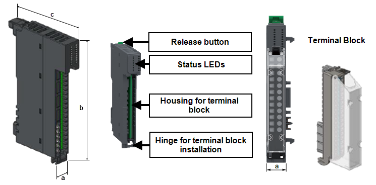
| a |
15 mm (0.59") |
| b |
100 mm (3.94") |
| c |
66 mm (2.60") |
| c plus Terminal Block |
101.9 mm (3.98") |
|
RL2 Two Channel Relay Output Terminal Wiring
|
HAZARD OF ELECTRICAL SHOCK, EXPLOSION OR ARC FLASH
Failure to follow these instructions will result in death or serious injury
|
|
UNINTENDED EQUIPMENT OPERATION
Failure to follow these instructions can result in death, serious injury, or equipment damage
|
Tip - Where signal and power wiring cannot be separated, signal wiring should be shielded.
| 1 solid conductor |
0.2 to 2.5 mm² (American Wire Gauge (AWG) 24 - AWG 14) |
| 2 solid conductors |
0.2 to 1.5 mm² (AWG 24 - AWG 16) - both conductors must be the same cross section |
| 1 stranded conductor without ferrule |
0.2 to 2.5 mm² (AWG 24 - AWG 14) |
| 1 stranded conductor with single ferrule |
0.2 to 1.5 mm² (AWG 24 - AWG 16) |
| 2 stranded conductors with twin ferrule |
0.2 to 0.75 mm² (AWG 24 - AWG 20) |
Note - Minimum individual conductor size in stranded connectors when no ferrule is used is a cross section of 0.05 mm² (AWG 30).
Terminal block captive screws are not supplied tightened and must be tightened to 0.5 to 0.6 Nm (0.30 lb-ft) using a flat tipped screwdriver with a diameter of 3.5 mm (0.14"). Stripping length for all cable types is 10 mm (0.39").
RL2 wiring example showing two independent loads switched from EPM Data Management, one ac and one dc:
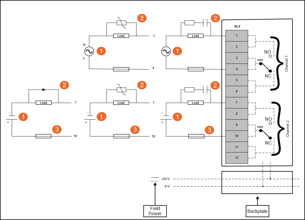
Note - The relay is shown de-energized.
| 1
|
External power supply 5 to 125 Vdc or 24 to 250 Vac |
| 2
|
Load external protection device. In integration, resistor and capacitor (RC) snubber (22nf 100Ω in series) can be ordered with your EPM Solution. Metal oxide varistor (MOV) for ac load and Diode/MOV for dc load can be included if appropriate for your application. |
|
| 3
|
External fast blow fuse appropriate for load, or protection to an equivalent level |
| NO
|
Normally open |
| NC
|
Normally closed |
|
|
|
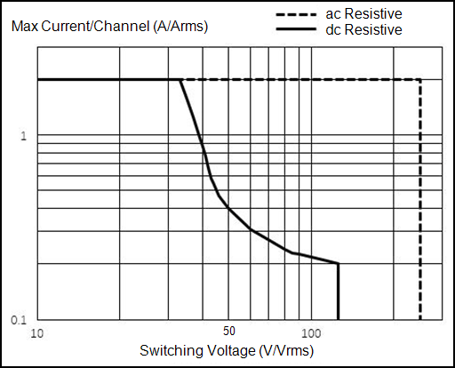
Load Graphs for Relay
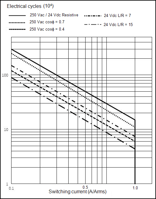
Note - Differences in load current, ambient temperature, load type and switching frequency can impact the number of operations.
|
|
Status LEDs
| Module is energized, configured and operational. |
Green |
Off |
Off |
| Channel is activated |
Green |
Off |
Green |
| Channel is deactivated |
Green |
Off |
Off |
| 24 Vdc field power error detection |
| Sensor power supply error detection |
|
Green |
Red - Regular flash (one flash per second) |
Off |
| No power |
Off |
Off |
Off |
| Module detects a system error |
Off |
Red |
Off |
| Module was not configured during initialization |
Green - Slow flash (one flash per 2 seconds) |
Off/Red - Slow flash (one flash per 2 seconds) |
Off |
| Firmware is being updated |
Green - Regular flash (one flash per second) |
Off |
Off |
Last Update - September 2026

 DANGER
 WARNING