Configuring a Digital Input Channel
A Digital Input Channel generates a digital input based on the configuration.
To configure a Digital Input Channel:
-
From the EPM User Interface screen, select Options
 - Device I/O - Hardwired I/O: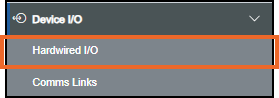
-
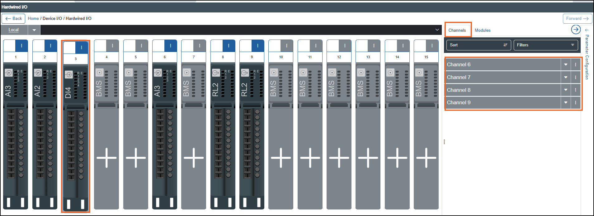
The Hardwired I/O screen displays, select the required Digital Input module from the left-hand side and the associated channels display on the right-hand side in the Channels tab:
-
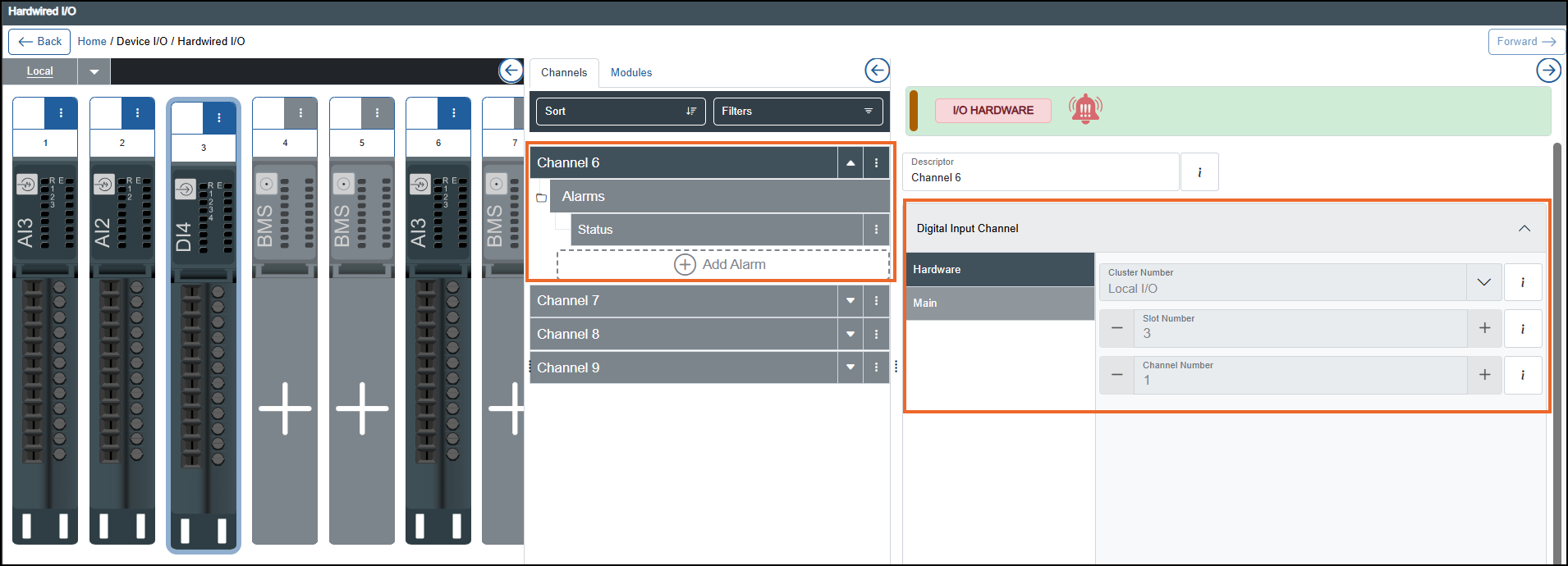
Select the required Digital Input Channel and the properties display on the right-hand side:
-
If you are not already in Configuration lock, the Configuration lock screen displays
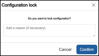
Enter a reason if required and then select Confirm
 . The system configuration is now locked pending the submission of your update and the Configuration Locked
  icon displays on the status bar.Note - Configuration lock does not affect the operation of the EPM device.See Configuration Lock for details.
 -
Complete as required:
-
Digital Input Channel - Select Expand
 if it does not expand automatically:
-
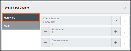
Hardware:
-
Cluster - Cluster where the module is plugged in, for example, Local I/O.
-
Slot Number - Slot number (1…n) where the module is plugged in.
-
Channel Number - Channel number (1…n) in the module.
-
-
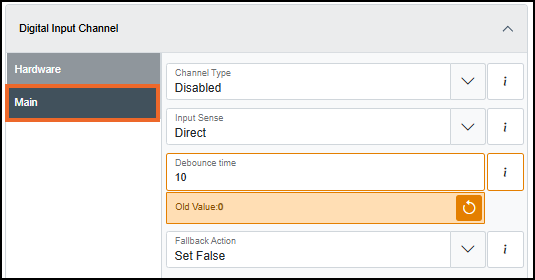
Main:
-
Input Type - Select the configuration type of the channel:
-
Off - Channel is disabled.
-
IEC Type 2 - IEC Type 2 Channel is enabled.
-
IEC Type 3 - IEC Type 3 Channel is enabled.
-
-
Input Sense- Select how the electrical input is interpreted in relation to the behavior of the Digital Input (DI):
-
Direct
-
When the contact is open or logic input is electrically low, the DI is False.
-
When the contact is close or logic input is electrically high, the DI is True.
-
-
Inverted
-
When the contact is open or logic input is electrically low, the DI is True.
-
When the contact is close or logic input is electrically high, the DI is False.
-
-
-
Debounce time - Enter the minimum time a change of input state must persist to affect Digital Input.
Enter number of days in d, hours in h, minutes in m, seconds in s and milliseconds in ms or use the Up
 and Down
  arrows to set the value. Select Apply
  , or Cancel to exit
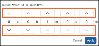 Tip - A single select moves the numbers one at a time, a long hold moves through the numbers quickly.
 -
Fallback Action- Select the behavior when the Digital Input (DI) status is bad, for example, when there is a communication issue:
-
Set False - The DI is set to Open.
-
Set True - The DI is set to Closed.
-
Hold - The DI is held until the status is good again.
-
-
-
-
-
From the Chart and presentation settings, select Expand
if it does not expand automatically, and then complete the following:-
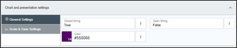
General Settings:
-
Closed String - Enter the text to represent the digital output Closed state.
-
Open String - Enter the text to represent the digital output Open state.
-
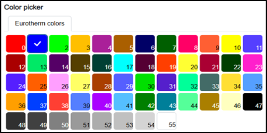
Color - Select a color from one of the 56 available colors:
-
-
Scale & Zone Settings:
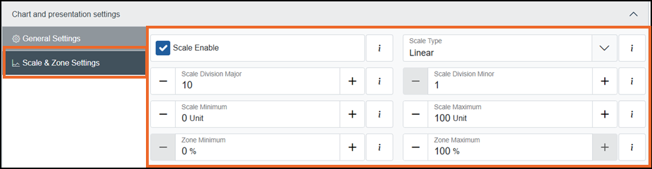
To set the chart scale and zoning for this channel:
-
Scale Enable - Tick to enable scale configuration and specify the scale type and the number of divisions required:
-
Scale Type (available only when Scale Enable is enabled) - Select one of the following options:
-
Logarithmic - Divisions are displayed using a logarithmic scale. This option is suitable for analyzing data spanning multiple orders of magnitude.
-
Linear - Divisions are displayed at equal intervals. This option is ideal for displaying uniformly distributed data:
-
Scale Division Major (available only when Scale Type is Linear) - Enter a value, or use the Plus
 and Minus
  to set the major divisions to be included on the chart (valid range 1 to 20).
 -
Scale Division Minor (available only when Scale Type is Linear) - Enter a value, or use the Plus
and Minus to set the minor divisions to be included on the chart (valid range 1 to 20).Note - Scale divisions have no impact on a chart grid, they are only for scale. The grid on the chart is defined by the division settings on the group, see Configuring Groups Settings for details.
-
-
-
-
Scale maximum (Unit) - Enter a value, or use the Plus
and Minus to set the upper limit of the scale's range. -
Scale minimum (Unit) - Enter a value, or use the Plus
and Minus to set the lower limit of the scale's range. -
Zone maximum (%) - Enter a value, or use the Plus
and Minus to set the percentage offset for the upper limit of the scale and trendline relative to the top of the chart (valid range 5 to 100). -
Zone minimum (%) - Enter a value, or use the Plus
and Minus to set the percentage offset for the lower limit of the scale and trendline relative to the bottom of the chart (valid range 0 to 95).Note - The minimum value must be less than the maximum value by 5 or more.Tip - The Zone settings offset a scale and its associated trendline relative to the chart grid. This is useful when displaying multiple trends with similar value ranges, which would otherwise overlap and become difficult to distinguish. For example, several digital trends switching between 0 and 1 can overlap, making them difficult to distinguish unless each is defined a different Zone.
-
-
 to configure an alarm on this channel, see Configuring an Alarm for further details.
Once complete, select Review pending changes  screen to review updates to the configuration, and submit them. See Reviewing and Submitting Changes for details if required.