Installing your EPM-07
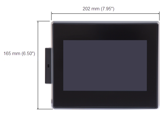
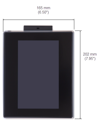
The EPM-07 display offers a landscape and portrait mounting with integrated human machine interface (HMI) and nine slots for Input/ Output (I/O) modules.
To install an EPM-07:
-
Clean and smooth the enclosure cutout and surrounding surface to avoid rough edges that could damage the device. This ensures a good seal during installation.
See Prerequisites for Installing your EPM Device for cutout dimensions. -
Unpack your device, see Unpacking your EPM Device(s) for details.
-
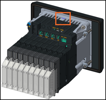
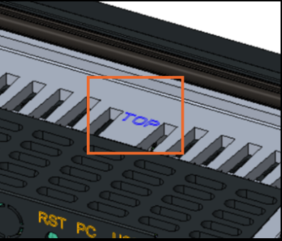
Insert the device through the enclosure aperture ensuring the TOP mark is at the top:
-
Locate the four panel grub screw fasteners, two on the left and two on the right-hand side of the device. Loosen them and rotate the arms away from the unit using a 3 mm (0.12") hexagonal driver, tighten the fasteners to a torque
 Torque - Torque is a twisting force that makes something turn or rotate. When you push on a door far from the hinges, it’s easier to open. That turning effect is torque. Torque depends on how hard you push (force) and how far from the pivot you push (distance from the hinge/axis).
Formula in words:
Torque = force × perpendicular distance from the pivot. of 1 Nm (0.74 lb-ft) with a torque driver. Tighten progressively in a star pattern. Begin at low torque, increase gradually to the maximum and make final passes at 1 Nm to confirm none have loosened.Note - Do not exceed 1 Nm (0.74 lb-ft) as this can damage the device.
Torque - Torque is a twisting force that makes something turn or rotate. When you push on a door far from the hinges, it’s easier to open. That turning effect is torque. Torque depends on how hard you push (force) and how far from the pivot you push (distance from the hinge/axis).
Formula in words:
Torque = force × perpendicular distance from the pivot. of 1 Nm (0.74 lb-ft) with a torque driver. Tighten progressively in a star pattern. Begin at low torque, increase gradually to the maximum and make final passes at 1 Nm to confirm none have loosened.Note - Do not exceed 1 Nm (0.74 lb-ft) as this can damage the device.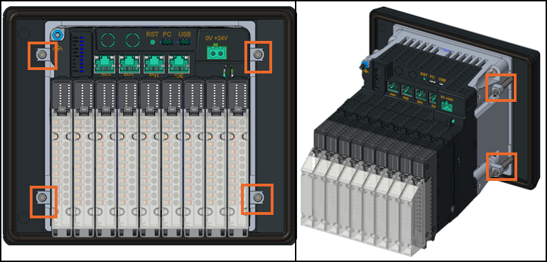 Note - To achieve IP66 or UL50E Type 4X rating, ensure the seal is properly compressed by tightening all the screws to the recommended torque. The maximum bezel gap between the panel and the device should be 1 mm (0.04") at the corners. Use a feeler gauge to measure the gap after fitting and check it regularly throughout the device's lifetime. Use a torque driver to re-adjust the screws. See Regular EPM Maintenance Tasks for details.
 -
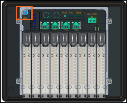
Install the Functional Earth (FE
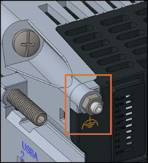
Functional earth (FE) - Ensures the proper functioning of electronic equipment by providing a stable reference point. It is used in electrical systems for operational purposes, for example, reducing electrical noise and improving signal integrity.) connection. The location of the FE is the same for both mounting options:-
Undo and remove the FE nut and washer.
-
Prepare a short length wire with a cross section of 0.75 to 2.5 mm² (AWG 18 to 13) and crimp one end into a suitable 4 mm (0.16") internal diameter ring terminal.
-
Place the terminal ring onto the FE stud.
-
Replace and tighten the FE nut and washer to a torque of 0.5 to 0.6 Nm (0.37 - 0.44 lb-ft).
-
Connect the other end of the wire to the system ground:
 WARNING
EQUIPMENT OPERATION HAZARD
Ensure the link between the device’s FE terminal and protective earth ground is as short as possible.
Failure to follow this instruction can result in death, serious injury or equipment damage
Note - A short link helps to achieve the best electromagnetic compatibility (EMC) performance and reduces emissions by protecting against electromagnetic interference (EMI) and radio frequency interference (RFI). -
-
If the I/O modules and terminal blocks are not fitted on receipt of your device, they should now be fitted. To fit I/O:
-
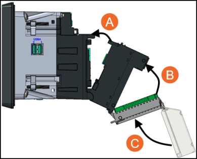
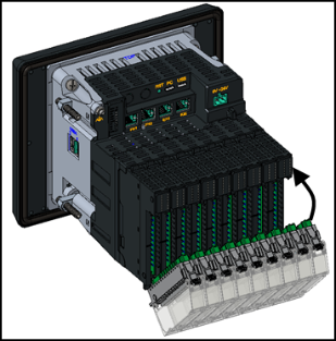
Attach the module - Hook the lower part of the module on to the device and then press the module upwards until it clicks into place at the top.
-
Connect the Terminal Block - Hook the lower part of the terminal block on to the device then press it until it clicks into place.
-
Secure the Plastic Cover - Hook the plastic cover on to the top of the terminal block, then press downwards until it clicks into place:
 Tip - The clear cover of the terminal block includes designated space for inserting a paper label with dimension 65 × 10.7 mm (2.56 × 0.42 in), thickness 0.2 mm (0.008 in).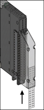
Note - The label shown is not supplied with the product and is intended for demonstration purposes only.Note - When Installing Digital Input modules in Slots 1-4, ensure the total current draw per slot does not exceed 250 mA including any external sensors powered by the DI modules. For slot 5-9, the maximum combined current draw is 2800 mA.
 DANGER
HAZARD OF ELECTRICAL SHOCK, EXPLOSION OR ARC FLASH
-
Do not exceed the device’s ratings.
-
Ensure all cables and wiring harness are secured using a relevant strain relief mechanism.
Failure to follow these instructions will result in death or serious injury
 WARNING
UNINTENDED EQUIPMENT OPERATION
-
Ensure wires are routed to minimize the pick-up of Electromagnetic interference (EMI) keeping cable lengths to a minimum.
-
Only use copper cables (except for the thermocouple wiring).
Failure to follow these instructions can result in death, serious injury, or equipment damage
Tip - Where signal and power wiring cannot be separated, signal wiring should be shielded.Terminal Wiring Cross Section 1 solid conductor 0.2 to 2.5 mm² (American Wire Gauge (AWG) 24 - AWG 14) 2 solid conductors 0.2 to 1.5 mm² (AWG 24 - AWG 16) - both conductors must be the same cross section 1 stranded conductor without ferrule 0.2 to 2.5 mm² (AWG 24 - AWG 14) 1 stranded conductor with single ferrule 0.2 to 1.5 mm² (AWG 24 - AWG 16) 2 stranded conductors with twin ferrule 0.2 to 0.75 mm² (AWG 24 - AWG 20) Note - Minimum individual conductor size in stranded connectors when no ferrule is used is a cross section of 0.05 mm² (AWG 30).Terminal block captive screws are not supplied tightened and must be tightened to 0.5 to 0.6 Nm (0.30 lb-ft) using a flat tipped screwdriver with a diameter of 3.5 mm (0.14"). Stripping length for all cable types is 10 mm (0.39").
The following I/O modules are available for use with EPM Data Management:
Select the module required for wiring details and useful links:
-
AI3 - 3 Channel Isolated Universal Analog Input Module, see AI3 - 3 Channel Isolated Universal Analog Input Module Quick Links for details.
-
AI2 - 2 Channel Isolated Analog Input Module, see AI2 - 2 Channel Isolated Analog Input Module Quick Links for details.
-
DI4 - 4 Channel Digital Input Module, see DI4 - 4 Channel Digital Input Module Quick Links for details.
-
RL2 - 2 Channel Relay Output Module, see RL2 - 2 Channel Relay Output Module Quick Links for details.
-
BMS - Blanking Module (Single Width), see BMS - Blanking Module Quick Links for details.
-
-
Select from the following options to expand the details:
24 Vdc without optional Power Supply Unit (PSU)
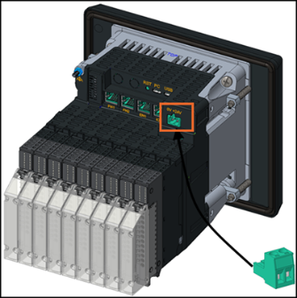
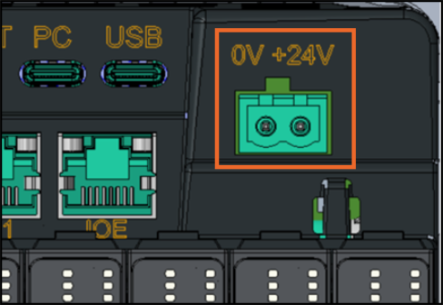
Strip the 24 Vdc cables, insert the 0 V+24 V connector fully into the 2-way 5.08 mm connector, tighten the terminal screws to 0.5 to 0.6 Nm (0.37–0.44 lb-ft) and then plug the connector into the unit:
Description Specification Nominal wire cross section for a single flexible wire 1.3 to 2.5 mm² (AWG 16 to AWG 14) Nominal wire cross section for two flexible wire of same cross-section 0.2 to 1.5 mm² (AWG 24 to AWG 16) Stripping length 7 mm (0.276") Tightening torque 0.5 to 0.6 Nm (0.37 - 0.44 lb-ft) See EPM Data Management - Technical Data Sheet for details.24 Vdc with optional PSU
Ensure that the 24 Vdc connector terminal screws on the 2-way 5.08 mm connector are tightened to 0.5 to 0.6 Nm (0.37–0.44 lb-ft). This is the single power supply for the EPM-07 unit.
To connect the PSU:
-
Align and insert the two top hooks with the right-hand side slots in the panel fastener recess.
-
Pivot the unit down until it rests against the device.
-
Push the PSU towards the unit until it clicks into place and sits flat.
-
Rotate the locking screws 90 degrees clockwise towards the closed padlock symbol
 using a 6ˣ1 mm slotted screwdriver or equivalent until it clicks.
 -
Plug the 24 Vdc output from the PSU into the device:
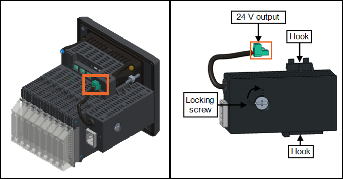
100/230 Vac optional power supply module
Connect the IEC C13 female connector into the IEC C14 male connector:
Note - The C13 connector should be wired using IEE compliant mains cable rated for a minimum of 10 A, 300 Vac and 105 °C.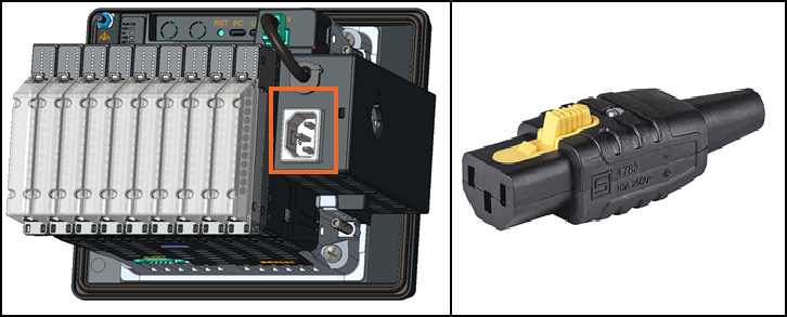
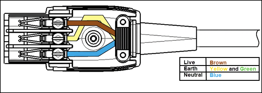
Description Specification Cable type H05VV-F Cable diameter minimum Ø 7.6 mm Cable diameter maximum Ø 9.4 mm Wire size minimum 3 ˣ 0.75 mm2 (AWG 18) Wire size maximum 3 ˣ 1.50 mm2 (AWG 15) Maximum torque for terminal screws 0.5 Nm (0.37 ft-lb) Maximum torque for cable clamps screws 0.3 Nm (0.22 ft-lb) Maximum torque for cover screws 0.8 Nm (0.59 ft-lb) -
-
Now connect any RJ45 connectors into the sockets required:
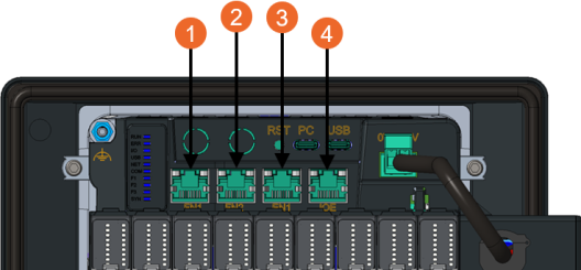
Key Description 1 - Field Network Field Network (FN) - A system of interconnected devices that manage and control physical processes and equipment. These networks are crucial in various applications, including industrial environments. (FN1)Connects the EPM device to other process equipment, for example, PLC/PAC and analyzers, using a choice of industrial control protocols. Ports FN1 and FN2 are connected by an internal switch and share the same IP address 2 - Field Network (FN2) Connects the EPM device to the same field network as FN1 3 - Enterprise Network Enterprise Network (EN) - Provides connectivity among users, devices and applications. They can include local area networks (LANs), wide area networks (WANs) and connections to the cloud. (EN1)Connects the EPM device to an IT or Enterprise network 4 - Input/Output Extender ( IOE) Pending future development Note - Field Network and Enterprise Network should be kept separate. We recommend you do not access one from the other.See Configuring Networks for details on setting up your EPM network settings. -
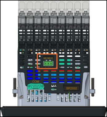
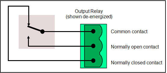
(Optional) The integral Watchdog/User relay always opens on Watchdog failure of the device and can also be driven by your application. If this relay is required, connect the screw connector located on the base of the device. Tighten this 3-way 5.08 mm (0.2") pitch connector to 0.5 to 0.6 Nm (0.37 - 0.44 lb-ft) torque to ensure connection to the relay contacts:
-
(Optional) Connect the Universal Serial Bus (USB) Type-C socket:
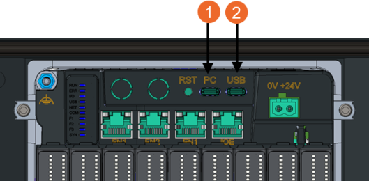
Key Description 1 - PC Currently inactive. Reserved for future development.
2 - USB This port connects to external mass storage devices, for example, USB memory sticks or portable hard drives. It uses a type C connector and supports USB 2.0 protocol, not USB-C standard. It provides up to 500 mA for storage devices. The recommended cable length is less than 1.5 m (4.92 ft). Note - USB-C interfaces should be treated as controlled external access points and only used where operationally necessary. Access via USB-C should be aligned with your organizational policies governing external device connectivity. Connections should not be left permanently connected unless explicitly required and risk-assessed. Extender cables should be shielded and not exceed 1.5 m (4.92 ft) in length. Where USB-C ports are exposed, for example, panel-mounted, they should be physically protected and implemented with appropriate environmental (IP) ratings. -
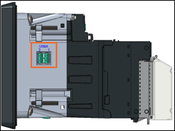
(Optional) Use the USB type-A ports on the left-hand side of the device to connect any peripherals, for example, keyboard, mouse or bar code reader. This port supports USB 2.0 standard protocol and is backward compatible, providing up to a maximum of 500 mA for storage devices:
NOTICE RISK OF DATA LOSS OR CORRUPTION
The maximum length of any USB cable is 1.5 m (4.92 ft).
Failure to follow this instruction can result in data loss
-
After installation, confirm all connections are secure. Connect to a stable power source, switch on and allow the unit to fully initialize. Verify that indicator LEDs and display outputs confirm normal operation before proceeding with configuration.
Last update - July 2026